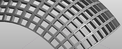
The new paneling functionality in Revit 2010 does some pretty new and fun stuff. Especially compared to the limitations of the old curtain panels. You can do non-planar, patterned, and all sorts of crazy, expensive stuff. One problem I hear about is people having difficulty making seamless edges. They make a nice clean panel and the edges look like Thing from the Fantastic Four. Out of the Box functionality is going to give you shapes like this:
 When what you might really want is this:
The problem is that, unless you tell the panel otherwise, your geometry is going to extrude from the face of your panel relative to some calculated normal of the individual panel, and not have any relationship to it's neighbors. What you might want is a shared edge, which means a shared vector based on the edge condition, not the overall panel condition. In section, the difference is like this:
This video shows how to get the relationship that creates a seamless edge. The principle is that you want to build your geometry based on the planes defined by points, rather than on the overall plane of the panel.
You stole my post!!! :)
ReplyDeleteI've got three videos done for this very issue, since you were so helpful!
Now I'm gonna have to find something else cool to post on. ;)
Cheers,
-R
I love this! thank you,
ReplyDeletethough I did run into problems trying to add a void in the middle to get a frame. would you use a void for that?
You can use a void to make a frame, but I'm guessing that it ends up not always cutting the proper hole when the frame is really deformed? I can do a seperate post for this situation.
ReplyDeleteWas just wondering if you will be interested in a little experiment of importing a complex dwg into a massing family for the creation of solid element in Revit?
ReplyDeletelet me know if you do:
eldada@fparch.com.au
thanks :)
Hi
ReplyDeleteI know this is a bit old, but I follow your tutorial and is great. I found a solution for the corners. Create more dots towards the inside, give them parameters and then instead of making a face extrusion, make 2 faces, one outside and one inside and the join, then do the same in each side. This way you will have nice corners.
Zach, awesome post. I shared it with our class because I'm pretty sure everyone was having this problem.
ReplyDeleteI had the same question as someone earlier; how can I add a void to this? I am trying to make an interior hole whose size changes with a bitmap. the simple blend you show here works fine but as soon as I add the void in the middle it freaks out and I get the "Can't make type" error.
any ideas?
Laura,
ReplyDeleteYou can try something like the image shown at the bottom of this post. http://buildz.blogspot.com/2009/05/seamless-mullions.html
You will need to have a void that is larger than the solid it is cutting. You can also try making a void on workplane of a ref line diagonally connecting 2 of the adaptive points of the panel familiy.
What can you do when you have a complex shape that when subdivided it created different pannels... and thus when I want to apply the poit base family it does it per pannel but it does not joint the corners of the next panel
ReplyDeleteHi Pedro,
ReplyDeleteDo you have any images of what you are trying to do?
Zach, I have a question about this exercise: Because you have reference points hosted to the adaptive points with the offset value occuring in the z-direction, when applied to the host surface, don't each of the components have a different depth relative to the next because its occuring in a single direction? I've tried this on a facet surface where I had the offset happing inward and I ended up with different thicknesses at each face. Is there a way to do this where the thickness is always the same?
ReplyDeletehi, plz... when I make the voids inside, the are rotated and miss located... any clues plz
ReplyDelete